AxelGlobe Image Specification sheet
Change history
| version | revision date | revised content | remarks |
|---|---|---|---|
| 1.00 | 2020-12-01 | First version | |
| 1.10 | 2021-06-10 | Reflect service update | |
| 1.20 | 2021-08-27 | Add section 2.1. Revised definition of band/layer | |
| 1.30 | 2021-10-13 | Changed File contents (section 3.2.3 and 3.3.3) | |
| 1.40 | 2021-12-13 | Changed File contents (section 3.4) | |
| 1.50 | 2023-03-01 | Added section 3.5. |
1. Introduction
1.1. Purpose of this document
This document explains remote sensing image products taken by GRUS satellite operated by Axelspace. The specifications of this image product are subject to change without prior notice.
1.2. About AxelGlobe
AxelGlobe is the Earth observation infrastructure for a new era. It will have the ability to image the whole civilized world with a spatial resolution of 2.5 m every day. Its advantage is not just up-to-date information it will provide, but also in the collection of its past data. Comparing older images and studying their evolution can lead to invaluable insights and predictions for the future. As of June in 2021, there are five GRUS satellites that composes the AxelGlobe constellation, and the GRUS series will continue to be added in the future.
2. About GRUS satellite
GRUS is the name of the micro earth observation satellite that constitutes the AxelGlobe constellation. The GRUS satellite is equipped with two telescopes, which contributes to expanding the observation width. As a result, It has achieved both a high resolution of 2.5 m and a wide observation range of 55 km or more.
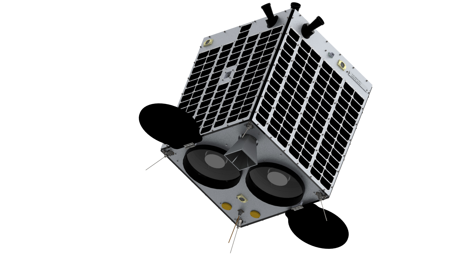
The details of the GRUS satellite are described in Table 1.
Table 1. GRUS satellite system specifications
| Item | Contents | ||
|---|---|---|---|
| Number of satellite | 5 (as of Aug. 2021) | ||
| Design life | Over 5 years | ||
| Orbital altitude | 585 km, Sun-synchronous sub-recurrent orbit | ||
| Equator passage time | 10:40-11:00 (local time) | ||
| Spectral band | Band ID | Name | Wavelength range (nm) |
| band0 | Panchromatic | 450-900 nm | |
| band1 | Blue | 450-505 nm | |
| band2 | Green | 515-585 nm | |
| band3 | Red | 620-685 nm | |
| band4 | Red Edge | 705-745 nm | |
| band5 | Near Infrared | 770-900 nm | |
| Ground resolution (at nadir) |
Panchromatic: 2.5 m or less Multispectral: 5.0 m or less |
||
| Swath | 55 km or more | ||
| Longest collection length | 1,000 km | ||
| Sensor bit depth | 12-bit | ||
2.1 Spectral bands, relative response and ESUN
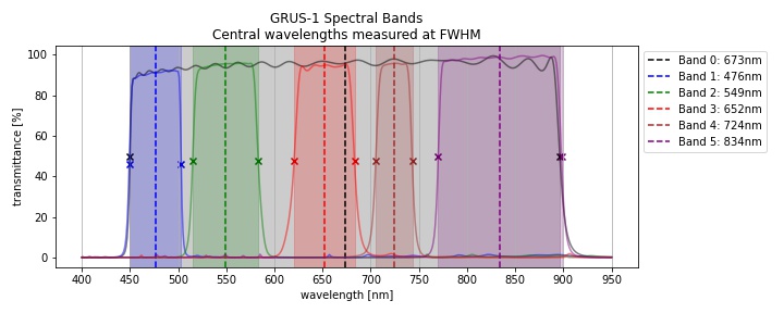
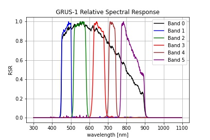
Data
3. AxelGlobe image product specification
3.1. GRUS image product
A summary of GRUS satellite image products provided by Axelspace is outlined in Table 2.
These image products consist of AxelGlobe Cells, measuring about 5 km × 5 km per tile. This product is intended for applications that require accurate location information and map projection images. The image product is processed with sensor correction, geometric correction, and map projection. In addition to automatically extracting the ground control points (GCP) from the high positional accuracy base map using our unique matching technology, we also combine conventional methods for areas where the GCP extraction is difficult. In applying correction processing, the location accuracy of the product depends on the GCP used and varies from region to region.
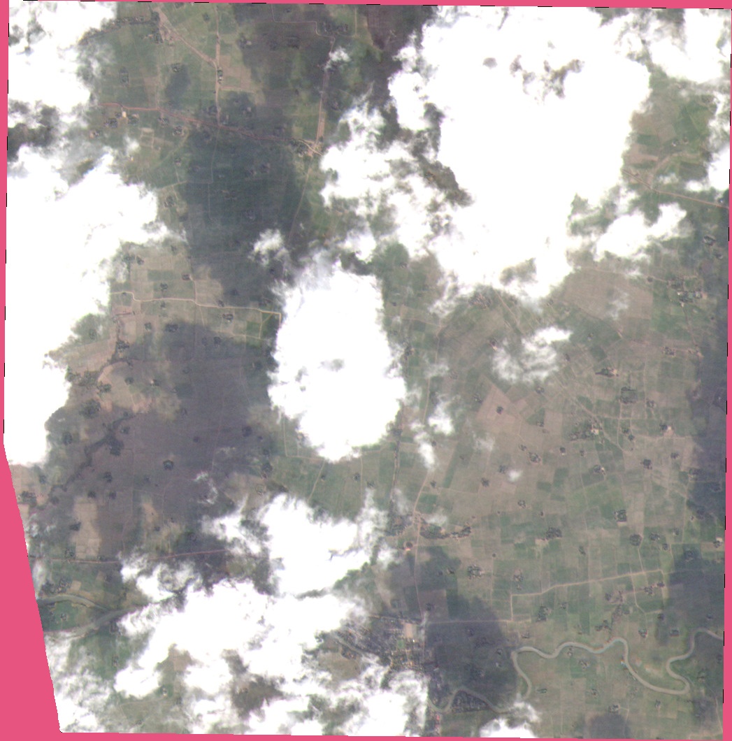
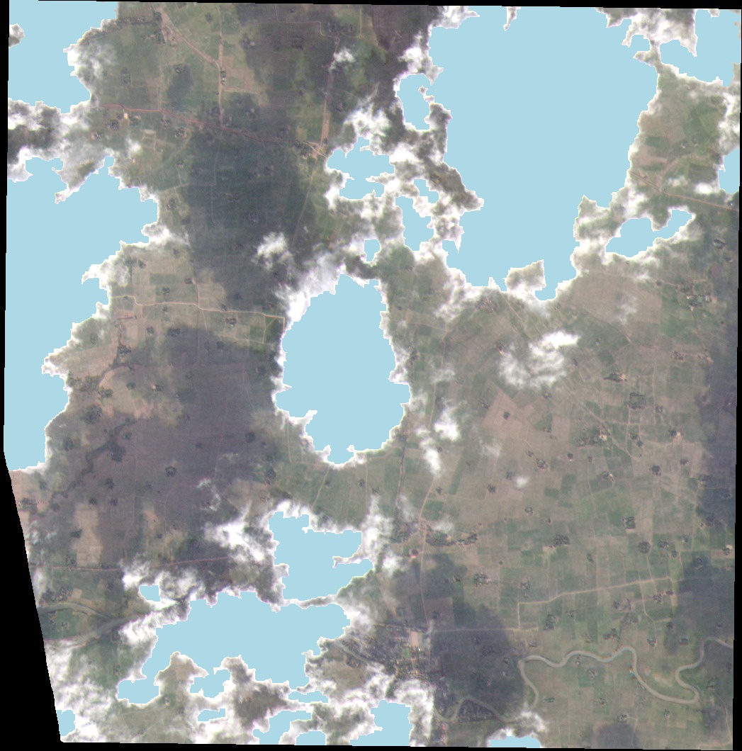
In addition, mask data that indicates areas unsuitable for analysis are provided as an unusable data mask file(UDM file). The UDM marks pixels with missing data, areas falling outside the captured image boundary, or obscured by clouds. The UDM file is available in products produced on Oct. 14, 2020 or later.
Table 2. GRUS satellite image product types
| Product name | content |
|---|---|
| Multispectral Image Products (MSI) | This product is processed with sensor and geometric correction. Pixel resolution is 2.5 m in panchromatic image and 5.0 m in multispectral image. Positional accuracy is aimed within 10-meter RMSE range. Relative/absolute radiometric correction is also applied. The pixel value for this data is obtained by scaling the reflectance at the top of the atmosphere to an unsigned 16-bit integer value. |
| Surface Reflectance Products (SR) | This product possesses the same attributes as the Multispectral Image Products but with the addition of atmospheric correction applied to each pixel value. |
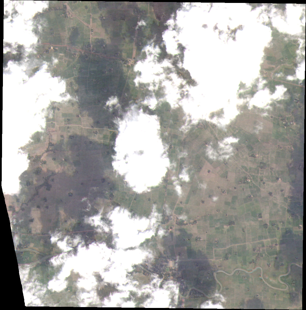
| True Color Image Products (TCI) | This product is processed with sensor, geometric correction, and pansharpening. Pixel resolution is 2.5 m. Positional accuracy is aimed within 10-meter RMSE. For visual enhancement purposes, this product has also been post-processed with color-correction technique. A pixel value is scaled into an unsigned 8-bit integer. |
The following figure shows pixels marked by an UDM file.
| TCI | Invalid data area (pink) | Cloud area (blue) |
 |
 |
 |
3.2. Multispectral Image Products (MSI)
Multispectral Image Products consist of panchromatic: has sensitivity in wide wavelength and 2.5m resolution, and multispectral: has sensitivity at different wavelength and 5 m resolution, bundled imaging products. In this image product, artefacts such as pattern noise caused by all sensors are corrected. The pixel value is then converted into Top-of-Atmosphere (TOA) reflectance values.
3.2.1. Multispectral Image Product specification
The Multispectral Image Products contains the datasets shown in Table 3.
Table 3. Multispectral Image Product specification
| Product attribute | Content | Description |
|---|---|---|
| Product configuration and format | Panchromatic imagery file |
16-bit panchromatic imagery data that is divided by AxelGlobe cell. GeoTIFF format or JPEG2000 format.
Layer assignment: |
| Multispectral imagery file |
16-bit multispectral imagery data that is divided by AxelGlobe cell. GeoTIFF format or JPEG2000 format.
Layer assignment: |
|
| Unusable Data Mask (UDM) file |
Binary image data that indicates the unusable region. GeoTIFF format or JPEG2000 format. The pixel resolution matches that of the product.
Layer assignment: Digital number assignment:
Layer1:
Layer2: |
|
| Metadata file | Metadata for panchromatic imagery file, multispectral imagery file, and unusable data mask file. JSON format. | |
| Product frame | AxelGlobe Cell |
Our global grid system is based on the AxelGlobe Cell measuring about 5 km x 5 km per tile. A buffer of about 100m (overlap area with adjacent cells) is added to each of the four sides. If the captured image does not fill the entire area of the cell, the unfilled area will be indicated with black pixels wherein No data value (0) is assigned. |
| Pixel resolution |
2.5 m (Panchromatic) 5.0 m (Multispectral) |
The actual ground sampling distance varies on the collection conditions (mainly due to the satellite roll angle), but a sampling process is applied to the specified pixel size when product is generated. |
| Bit depth | 16-bit unsigned integer |
GRUS satellite images are stored in the onboard memory as up to 12 quantized bits. Relative DN values obtained directly from the sensor are converted to reflectance value at the top of atmosphere by radiometric correction, and the result is scaled (10,000 times) to a 16-bit dynamic range. (* Refer to 3.2.4 Radiometric correction) |
| Resampling | Cubic Convolution | Performs resampling processing using the Cubic Convolution interpolation method, which uses the weighted average value calculated from the values of the 16 input cells around the output cell. This sampling method has the characteristic that the boundaries of data tend to be sharp. |
| Geometric correction | sensor telemetry | Internal detector geometric correction combining the virtual array with eight imagers |
| band-to-band registration | Band-to-band registration correction used to rectify misalignment between bands | |
| Geo-rectification | In geo-rectification, the characteristic terrain and features are extracted and paired between the captured image and the existing satellite image data (base map). The extracted terrain and features are matched with the reference points of each base map corresponding to the reference points. Processing is performed to reduce the positional deviation of the entire image with respect to the base map. | |
| Radiometric correction |
Correction of relative value difference of radiometric characteristics between detectors Undetected detector filling for null values from unresponsive detectors Conversion to reflectance values at the top of atmosphere based on calibration factors Scaling reflectance values at the top of atmosphere to 16-bit unsigned integer values (10,000 times) |
|
| Horizontal geodetic system | WGS1984 | |
| Projection | Universal Transverse Mercator projection (UTM) | UTM is a transverse Mercator projection that divides the earth into longitude zones every 6° eastward from the 180° meridian and projects the central meridian as the central meridian from the spheroid directly into the plane for each longitude band. Zones are determined by the south-west corner coordinates at the start of capture. |
3.2.2. File naming
Multispectral Image Products are named according to the following naming convention. The file name contains several components that help organize, categorize, and refer to the information contained in the product.
<SatelliteName>_<AcquisitionDatetime>_<ProductLevel>_<ImageType>_<CellID>.<Extention>
Table 4. File naming convention
| File naming component | Description | |
|---|---|---|
| <SatelliteName> | Satellite name abbreviation (e.g. : GRUS-1A = GRUS1A) | |
| <AcquisitionDatetime> | The collection start date and time in the yyyymmddhhmmss description format. (e.g.:Jan. 2, 2018 11:32:54 = 20180102113254) | |
| <ProductLevel> | L1C | |
| <ImageType> | Image type | Description |
| Panchromatic | PAN | |
| Multispectral | MSI | |
| Unusable mask file for panchromatic | PAN_UDM | |
| Unusable mask file for multispectral | MSI_UDM | |
| <CellID> | Unique ID of AxelGlobe Cell | |
| <Extention> | Extension of imagery file(e.g.:GeoTIFF:tif) | |
3.2.3. File contents
Details of the Multispectral Image Products are provided in the file contents shown below.
EULA_en.txt                                             # License agreement (English)
EULA_jp.txt                                             # License agreement (Japanese)
GRUS1A_20200811011052
├─ GRUS1A_20200811011052_L1C_MSI_N42092354.tif          # Multispectral imagery
├─ GRUS1A_20200811011052_L1C_MSI_N42092355.tif          # Multispectral imagery
├─ GRUS1A_20200811011052_L1C_MSI_metadata.json          # Meta data for multispectral imagery
│
├─ GRUS1A_20200811011052_L1C_MSI_UDM_N42092354.tif      # UDM for multispectral imagery
├─ GRUS1A_20200811011052_L1C_MSI_UDM_N42092355.tif      # UDM for multispectral imagery
├─ GRUS1A_20200811011052_L1C_MSI_UDM_metadata.json      # Meta data for UDM of multispectral imagery
│
├─ GRUS1A_20200811011052_L1C_PAN_N42092354.tif          # Panchromatic imagery
├─ GRUS1A_20200811011052_L1C_PAN_N42092355.tif          # Panchromatic imagery
├─ GRUS1A_20200811011052_L1C_PAN_metadata.json          # Meta data for panchromatic imagery
│
├─ GRUS1A_20200811011052_L1C_PAN_UDM_N42092355.tif      # UDM for panchromatic imagery
├─ GRUS1A_20200811011052_L1C_PAN_UDM_N42092354.tif      # UDM for panchromatic imagery
└─ GRUS1A_20200811011052_L1C_PAN_UDM_metadata.json      # Meta data for UDM for panchromatic
3.2.4. Radiometric correction
To ensure the radiometric quality of GRUS satellite image products, we regularly observe calibration sites around the world and perform relative/absolute radiometric calibration.
All GRUS satellite images are collected in 12-bit and stored in the satellite's onboard memory as an image data with up to 12 quantized bits. It is scaled to a 16-bit dynamic range by radiometric correction in the ground processing system. With this, the relative pixel DN value obtained directly from the sensor is converted to the reflectance at the top of the atmosphere (TOA) by absolute radiometric correction and stored as a 16-bit value after scaling.
The pixel value of the Multispectral Image Products can be converted to the TOA reflectance by the following formula.
      REF(i)=DN(i)* ScaleFactor(i)
      where ScaleFactor(i) = 0.0001

 where
 i: band id
 REF:TOA reflectance
 DN:pixel value
Besides, TOA reflectance(REF) can be converted to the TOA radiance by the following formula:
      RAD(i) = REF(i) * (ESUN * cos(90 - solar_elevation_angle)) / (PI * (sun_earth_distance^2))
 where
 i: band id
 REF: TOA reflectance
 RAD: TOA radiance
3.3. True Color Image Products (TCI)
The True Color Image Product is a product consisting of AxelGlobe Cell, measuring about 5 km × 5 km per tile. This product is intended for applications that require accurate location information and map projection images. The True Color Image Product is processed with sensor correction, geometric correction, and map projection. In addition to automatically extracting the ground control points (GCP) from the high positional accuracy base map using our unique matching technology, we also combine conventional methods for areas where the GCP extraction is difficult. In applying correction processing, the location accuracy of the product depends on the GCP used and varies from region to region.
True Color Image Products are tone-corrected and pansharpened imagery products optimized for visual applications. This image product corrects artefacts such as pattern noise caused by all sensors while pixel values are corrected for visual enhancement purpose. A file that indicates areas unsuitable for analysis is attached as a usable data mask file (UDM file). The UDM marks pixels with missing data, fall outside the captured image boundary, or are obscured by clouds.
3.3.1. True Color Image Product Specification
The True Color Image Product contains the corresponding datasets delineated in Table 5.
Table 5. True Color Image Product specification
| Product attribute | Content | Description |
|---|---|---|
| Product configuration and format | Pan-sharpened imagery file |
8-bit color-scaled pan-sharpened imagery data that is divided by AxelGlobe cell. GeoTIFF format or JPEG2000 format.
Layer assignment: |
| Unusable Data Mask (UDM) file |
Binary image data that is indicative of the unusable region. GeoTIFF format or JPEG2000 format.The pixel resolution matches that of the product.
Layer assignment: Digital number assignment:
Layer1:
Layer2: |
|
| Metadata file | Metadata for pan-sharpened imagery file and unusable data mask file. JSON format | |
| Product frame | AxelGlobe Cell |
Our global grid system is based on the AxelGlobe Cell measuring about 5 km x 5 km per tile. A buffer of about 100m (overlap area with adjacent cells) is added to each of the four sides. If the captured image does not fill the entire area of the cell, the unfilled area will be indicated with black pixels wherein No data value (0) is assigned. |
| Pixel resolution | 2.5 m | The actual ground sampling distance varies on the collection conditions (mainly due to the satellite roll angle), but a sampling process is applied to the specified pixel size when product is generated. |
| Bit depth | 8-bit unsigned integer | GRUS satellite images are stored in the onboard memory as up to 12 quantized bits. Relative DN values obtained directly from the sensor are tone-scaled to 8-bit for visual purpose. |
| Resampling | Cubic Convolution | Performs resampling processing using the Cubic Convolution interpolation method, which uses the weighted average value calculated from the values of the 16 input cells around the output cell. This sampling method has the characteristic that the boundaries of data tend to be sharp. |
| Geometric correction | sensor model | Optical distortion correction due to sensor optics |
| band-to-band registration | Band-to-band registration correction used to rectify misalignment between bands | |
| Geo-rectification | In geo-rectification, the characteristic terrain and features are extracted and paired between the captured image and the existing satellite image data (base map). The extracted terrain and features are matched with the reference points of each base map corresponding to the reference points. Processing is performed to reduce the positional deviation of the entire image with respect to the base map. | |
| Radiometric correction |
Correction of relative value difference of radiometric characteristics between detectors Undetected detector filling for null values from unresponsive detectors Scaling a 12-bit relative DN value to an 8-bit unsigned integer value by gamma correction |
|
| Enhancement | Dark Object Subtraction (DOS) | The dark pixels in the image are used to reduce noise such as water vapor and dust in the atmosphere. (Applies to images taken after July 7, 2020) |
| Horizontal geodetic system | WGS1984 | |
| Projection | Universal Transverse Mercator projection (UTM) | UTM is a transverse Mercator projection that divides the earth into longitude zones every 6° eastward from the 180° meridian and projects the central meridian as the central meridian from the spheroid directly into the plane for each longitude band. Zones are determined by the south-west corner coordinates at the start of capture. |
3.3.2 File naming
True Color Image Products are named according to the following naming convention. The file name contains several components that help organize, categorize, and refer to the information contained in the product.
<SatelliteName>_<AcquisitionDatetime>_<ProductLevel>_<ImageType>_<CellID>.<Extention>
Table 6. File naming convention
| File naming component | Description | |
|---|---|---|
| <SatelliteName> | Satellite name abbreviation (e.g. : GRUS-1A = GRUS1A) | |
| <AcquisitionDatetime> | The collection start date and time in the yyyymmddhhmmss description format. (e.g.:Jan. 2, 2018 11:32:54 = 20180102113254) | |
| <ProductLevel> | L1C | |
| <ImageType> | Image type | Description |
| Pan-sharpen | PSM | |
| Unusable mask file for Pan-sharpen | PSM_UDM | |
| <CellID> | Unique ID of AxelGlobe Cell | |
| <Extention> | Extension of imagery file(e.g.:GeoTIFF:tif) | |
3.3.3. File contents
Details of the True Color Image Products are provided in the file contents shown below.
EULA_en.txt                                             # License agreement (English)
EULA_jp.txt                                             # License agreement (Japanese)
GRUS1A_20200811011052
├─ GRUS1A_20200811011052_L1C_PSM_N42092354.tif          # Pan-sharpened imagery
├─ GRUS1A_20200811011052_L1C_PSM_N42092355.tif          # Pan-sharpened imagery
├─ GRUS1A_20200811011052_L1C_PSM_metadata.json          # Pan-sharpened imageryMeta data
│
├─ GRUS1A_20200811011052_L1C_PSM_UDM_N42092354.tif      # UDM for pan-sharpened imagery
├─ GRUS1A_20200811011052_L1C_PSM_UDM_N42092355.tif      # UDM for pan-sharpened imagery
└─ GRUS1A_20200811011052_L1C_PSM_UDM_metadata.json      # Meta data for UDM for pan-sharpened imagery
3.4. Metadata
The description of product metadata is shown in Table 7
Table 7. Metadata Description
| Section | Field 1 | Field 2 | Data type | Description |
|---|---|---|---|---|
| Company | ||||
| companyName | string | Company name | ||
| companyLocation | string | Main office location | ||
| contact | string | Contact number | ||
| copyright | string | Copyright | ||
| processorVersion | string | Software version of processor | ||
| bundlerVersion | string | Software version of data delivery | ||
| processDate | string | Product processing date | ||
| EOMetadata | ||||
| satelliteID | string | Unique ID assigned to the satellite | ||
| satelliteName | string | Official satellite name | ||
| orbitType | string | Types of satellite orbit | ||
| orbitInclinationAngle | double | Inclination angle of satellite orbit | ||
| orbitDirection | string | Direction the satellite in orbit is heading at the time of image acquisition | ||
| captureID | string | Unique ID corresponding to a capture event | ||
| acquisitionDateTime | ||||
| acquisitionStartDateTime | date |
Capture start date and time of the capture event. Describe it in ISO8601 extended format with delimiter |
||
| acquisitionEndDateTime | date |
Capture end date and time of the capture event. Describe it in ISO8601 extended format with delimiter |
||
| satelliteOffNadirAngleNominal | double | Nominal value of the off-nadir (degree) of the satellite at the time of the capture event | ||
| satelliteElevationAngleNominal | double | Nominal value of the elevation angle (degree) of the satellite at the time of the capture event | ||
| satelliteAzimuthAngleNominal | double | Nominal value of the azimuth angle (degree) of the satellite at the time of the capture event | ||
| solarElevationAngleNominal | double | Nominal value of the sun elevation angle(degree) at the collection event | ||
| solarAzimuthAngleNominal | double | Nominal value of the sun azimuth angle at the capture event | ||
| panchromaticRowGSDNominal | double |
Nominal value of ground sampling distance (GSD) at the row direction at the panchromatic sensor. Unit: meter |
||
| panchromaticColumnGSDNominal | double |
Nominal value of ground sampling distance (GSD) at the column direction at the panchromatic sensor. Unit: meter |
||
| multispectralRowGSDNominal | double |
Nominal value of ground sampling distance (GSD) at the row direction at the multispectral sensor. Unit: meter |
||
| multispectralColumnGSDNominal | double |
Nominal value of ground sampling distance (GSD) at the column direction at the multispectral sensor. Unit: meter |
||
| GSDUnits | string | Unit of GSD | ||
| resamplingAlgorithm | string | Resampling method used in production Processing: Cubic Convolution | ||
| radiometricCalibrationApplied | Boolean | Yes, No | ||
| earthSunDistance | double |
Distance between the center of the sun and the center of the earth Unit: Astronomical Unit[AU] |
||
| absoluteGain | ||||
|
Panchromatic Blue Green Red Red Edge Near Infrared |
double |
Gain parameter when converting the observed DN value into the TOA radiance [W⋅sr-1 ⋅m-2] Listed for each band |
||
| ESUN | ||||
|
Panchromatic Blue Green Red Red Edge Near Infrared |
double |
Extra-terrestrial solar irradiation Unit: [mW/m2] |
||
| productMetadata | ||||
| pansharpen | Boolean | Yes, No | ||
| bitsPerPixel | string | 1U, 8U, 16U | ||
| compressionType | string | NONE / DEFLATE / JPEG2000 | ||
| outputFormat | string | GeoTIFF/JPEG2000 | ||
| spatialReferenceSystem | ||||
| EPSGCode | Integer | EPSG code related to image geodetic system and projection | ||
| geodeticDatum | String | geodetic datum | ||
| projection | String | projection | ||
| projectionZone | String | projection zone | ||
| layerConfiguration | ||||
| layerX | String |
[Satellite image data]
[Other attached data] |
||
| valueInterpretation | For the following items, only unusable mask data are described | |||
| layerX | String | Described the pixel value interpretation in the Xth layer | ||
| imageTileMetadata | Repeat for the number of image files | |||
| imageName | string | image file name | ||
| cellID | string | Unique ID of AxelGlobe Cell | ||
| imageLocation | Tile range information units are based on product projection | |||
| type | string | Polygon | ||
| coordinates | list | Describes the coordinate values (X coordinate, Y coordinate) that make up the tile boundary in the order of bottom left, top left, top right, bottom right, bottom left | ||
| imageLocationUnits | string | Coordinates units | ||
| rowGSD | double | The pixel size in the row direction of the tile. Units are based on product projection | ||
| columnGSD | double | The pixel size in the column direction of the tile. Units are based on product projection | ||
| GSDUnits | string | Unit of GSD | ||
| numberRows | Integer | Number of lines (pixels) in the image | ||
| numberColumns | Integer | Number of columns (pixels) in the image | ||
| numberBands | Integer | Number of bands in the image | ||
| cloudCoverPercentage | double |
Cloud cover rate Unit : % only satellite image data are described |
||
3.5. Surface Reflectance Product
3.5.1. Surface Reflectance Product specification
The Surface Reflectance product is derived from the Multispectral image product with the addition of atmospheric correction which is used to convert top of atmosphere (TOA) reflectance values into bottom of atmosphere (BOA) reflectance. The intention of this product is to remove the impact of the atmosphere from image products in order to improve the accuracy of reflectance when compared with other datasets or actual surface reflectance values.
The specification of this product is the same as the specification for the Multispectral image product however in this case the reflectances values are bottom of atmosphere instead of top of atmosphere.
3.5.2. File naming
Surface Reflectance Image Products are named according to the following naming convention. The file name contains several components that help organize, categorize, and refer to the information contained in the product.
<SatelliteName>_<AcquisitionDatetime>_<ProductLevel>_<ImageType>_<CellID>.<Extention>
Table 4. File naming convention
| File naming component | Description | |
|---|---|---|
| <SatelliteName> | Satellite name abbreviation (e.g. : GRUS-1A = GRUS1A) | |
| <AcquisitionDatetime> | The collection start date and time in the yyyymmddhhmmss description format. (e.g.:Jan. 2, 2018 11:32:54 = 20180102113254) | |
| <ProductLevel> | L2A | |
| <ImageType> | Image type | Description |
| Panchromatic | PAN | |
| Multispectral | MSI | |
| Unusable mask file for panchromatic | PAN_UDM | |
| Unusable mask file for multispectral | MSI_UDM | |
| <CellID> | Unique ID of AxelGlobe Cell | |
| <Extention> | Extension of imagery file(e.g.:GeoTIFF:tif) | |
3.5.3. File contents
Details of the Surface Reflectance Image Products are provided in the file contents shown below.
EULA_en.txt                                             # License agreement (English)
EULA_jp.txt                                             # License agreement (Japanese)
GRUS1A_20200811011052
├─ GRUS1A_20200811011052_L2A_MSI_N42092354.tif          # Surface Reflectance imagery
├─ GRUS1A_20200811011052_L2A_MSI_N42092355.tif          # Surface Reflectance imagery
├─ GRUS1A_20200811011052_L2A_MSI_metadata.json          # Meta data for surface reflectance imagery
│
├─ GRUS1A_20200811011052_L2A_MSI_UDM_N42092354.tif      # UDM for surface reflectance imagery
├─ GRUS1A_20200811011052_L2A_MSI_UDM_N42092355.tif      # UDM for surface reflectance imagery
├─ GRUS1A_20200811011052_L2A_MSI_UDM_metadata.json      # Meta data for UDM of surface reflectance imagery
│
├─ GRUS1A_20200811011052_L2A_PAN_N42092354.tif          # Panchromatic imagery
├─ GRUS1A_20200811011052_L2A_PAN_N42092355.tif          # Panchromatic imagery
├─ GRUS1A_20200811011052_L2A_PAN_metadata.json          # Meta data for panchromatic imagery
│
├─ GRUS1A_20200811011052_L2A_PAN_UDM_N42092355.tif      # UDM for panchromatic imagery
├─ GRUS1A_20200811011052_L2A_PAN_UDM_N42092354.tif      # UDM for panchromatic imagery
└─ GRUS1A_20200811011052_L2A_PAN_UDM_metadata.json      # Meta data for UDM for panchromatic
3.5.4. Atmospheric correction
The process of atmospheric correction and conversion of top of atmosphere to bottom of atmosphere reflectance is carried out using the 6S radiative transfer equations and atmospheric data from the MODIS sensors. Lookup tables are generated using 6S and applied to the MSI product to perform the correction.
For more details, please see the Surface Reflectance product guide.